Installation of Spindle and VFD
Introduction
At CNC Online South Africa, we stock water-cooled and air-cooled spindle kits. This article will cover installation of these kits including wiring and interfacing with the DDCSV3.1 Controller.
Hardware Needed
1 x Spindle Kit (water or air-cooled)
Kit includes:
Spindle
VFD
Set of collets
Water pump and 5m pipe (water cooled only)
Spindle bracket (round spindle only)
1 x 10 meter 1.5mm 4 Core Shielded Cable (length depends on the size of your machine)
1 x EMI Filter
1 x GX20 Aviation Connector (not crucial)
1 x 10 meter 1.5mm 3 Core cabtyre (length depends on the size of your machine)
Product Links
Click here to view the air-cooled spindle.
Click here to view the water-cooled spindle.
Click here to view the EMI filter.
Click here to view the shielded spindle cable.
Click here to view the GX20 aviation connector.
Avoiding Interference Caused by Electrical Noise
Warning: I am not an electrician therefore some terms I use may not be correct. My articles are based on my experience with setting up spindles. If you are not comfortable working on high voltage circuits, please get an electrician to help you. I will not be held responsible for any incidents. Please unplug your machine from the wall socket before starting.
Using shielded cable is crucial for wiring the spindle to the VFD to avoid electrical noise. Electrical noise is an unwanted frequency that is caused during the transmission of alternating current. This noise causes havoc on signal cables such as limit switch signal cables and signal cables from your controller (such as false triggers on your limit switches). The shielding must be grounded to earth on the side closet to the VFD otherwise the noise will not be dispersed. Shielded cable is only used from the spindle to the VFD, normal cabtyre is used elsewhere.
How to ground shielded cable:
1. Strip the insulation back to reveal the braided mesh as seen below.

2. Pull the braid to one side and twist it. Soldier a cable onto the twisted shielding and ground it. Only ground on the side closest to the VFD.

The EMI filter is another precaution I have added to further reduce electrical noise. This is not necessary, but I highly recommend installing one. It is installed between the VFD and the wall socket.

Wiring Diagram
Below is a diagram on how to wire the spindle and VFD. All cables from the wall socket to the VFD and from the VFD to the DDCS V3.1 are cabtyre (not shielded) and the cable from the VFD to the Spindle is shielded.
Please note: if your spindle is rotating the incorrect direction, switch any two of the three cables spindle cable (spindle to VFD).

DDCS V3.1 to YL620-A VFD interface and Parameters
I will also explain how to connect the VFD to your DDCSV3.1 allowing spindle control from within the software. The wiring from the VFD to the DDCSV3.1 Controller can be seen in the image below (this is not necessary as the spindle can be controlled manually from the VFD’s control panel). Ensure your toolpath software (Vectric, Fusion 360, etc.) has the M3 and M5 command in the G-Code and the spindle speed parameter is correct.
Below is what the DDCSV3.1 to VFD wiring looks like: (diagram can be seen above)
Bridge GND to XGND on the VFD
VSO on DDCS to VI1 on VFD
M03 on DDCS to FWD on VFD
COM- on DDCS to GND on VFD

DDCSV3.1 Parameters
Change the parameters on your DDCSV3.1 as seen below:

VFD Parameters
We will now set the VFD parameters. Ensure your VFD parameters are set to the values seen on page 2 of the manual. The manual also explains the simple process of how to change parameters.
The only two parameters on the VFD that need to change to allow our VFD to interface with the DDCS is:
P00.01 - 1
P07.08 - 3
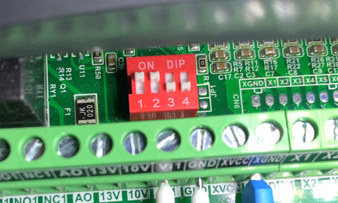
The dip switches on the VFD must be set as seen below:
Conclusion
Lastly we can mount the spindle and connect the water cooling pipes to the pump. Do not run the water-cooled spindle unless the pipes are connected to the water pump which is submerged in a bucket of water and the pump is on. We will soon be releasing an affordable closed loop cooling system for the water-cooled spindles. This will remove the need for a bucket of water lying on your shop floor.
If you require any assistance you can email me matthew@cnconline.co.za and I will assist you where I can.
Happy CNCing!!